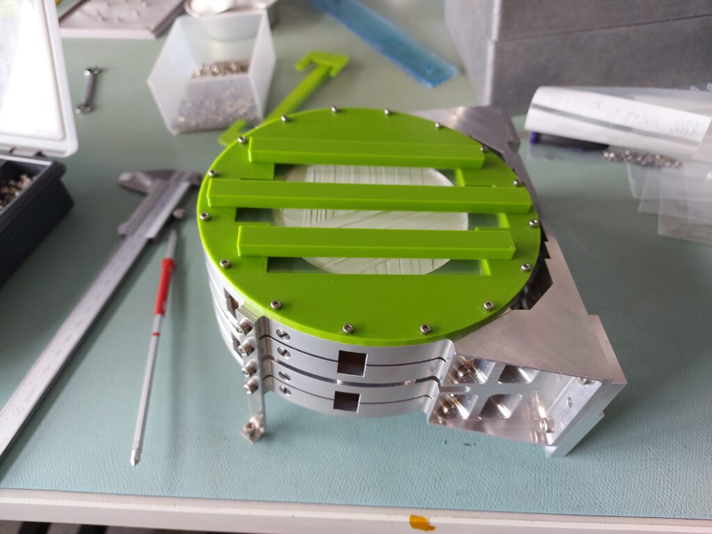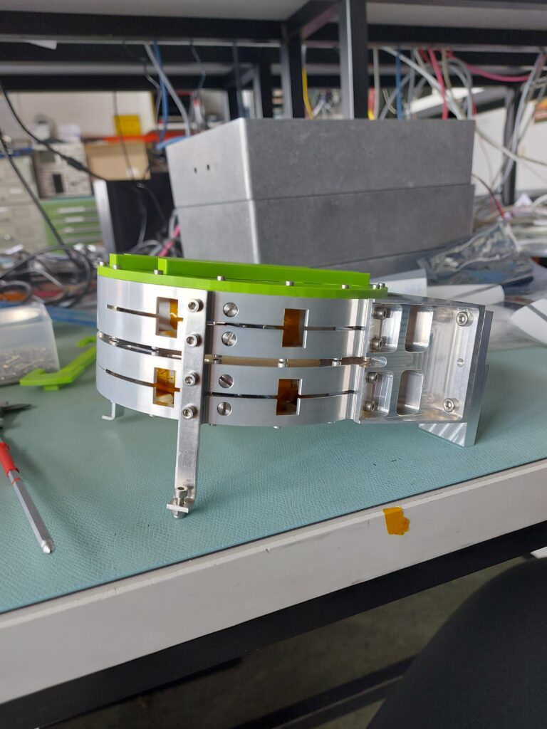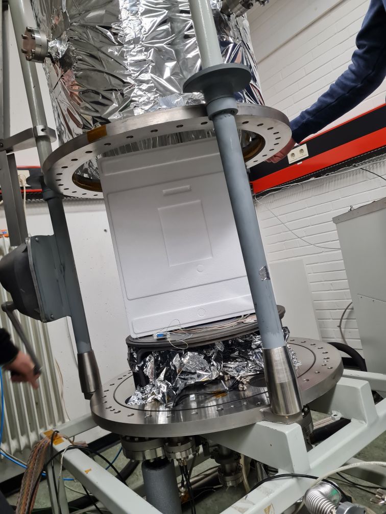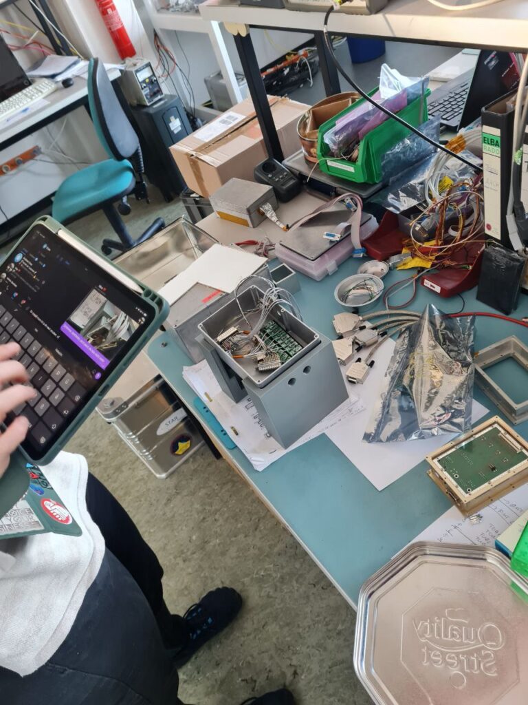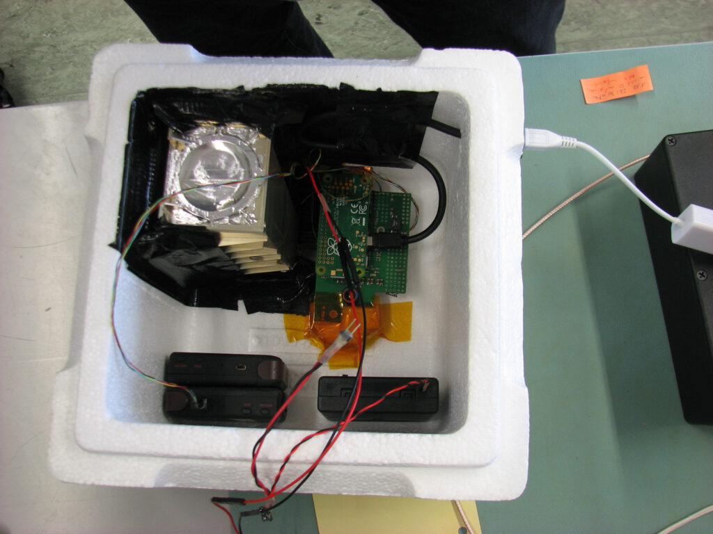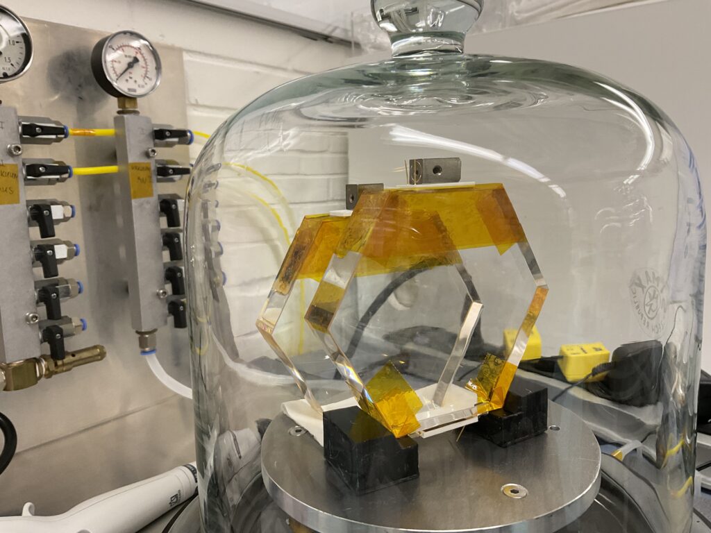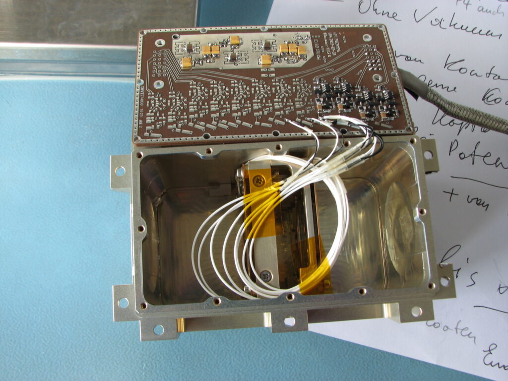
The first slices of the SETH sensor head is fully integrated and operational.
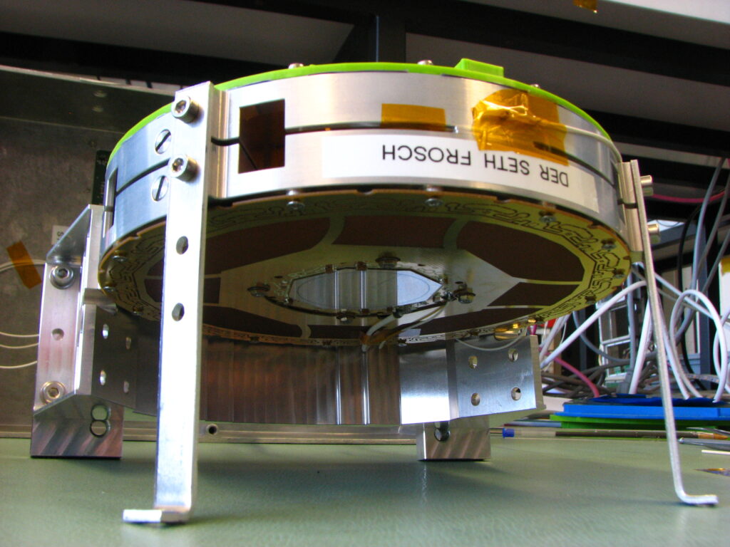
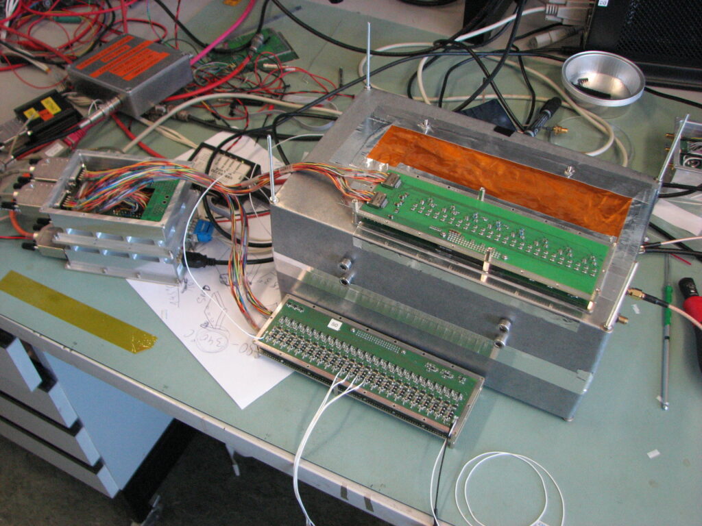
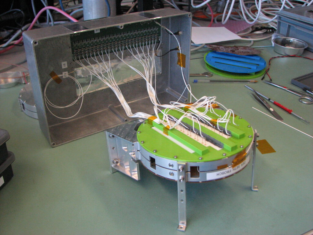
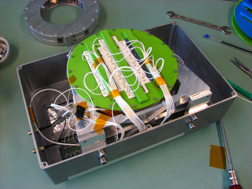
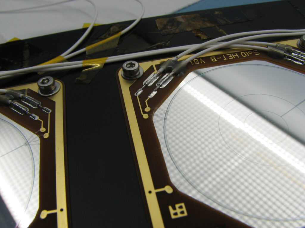
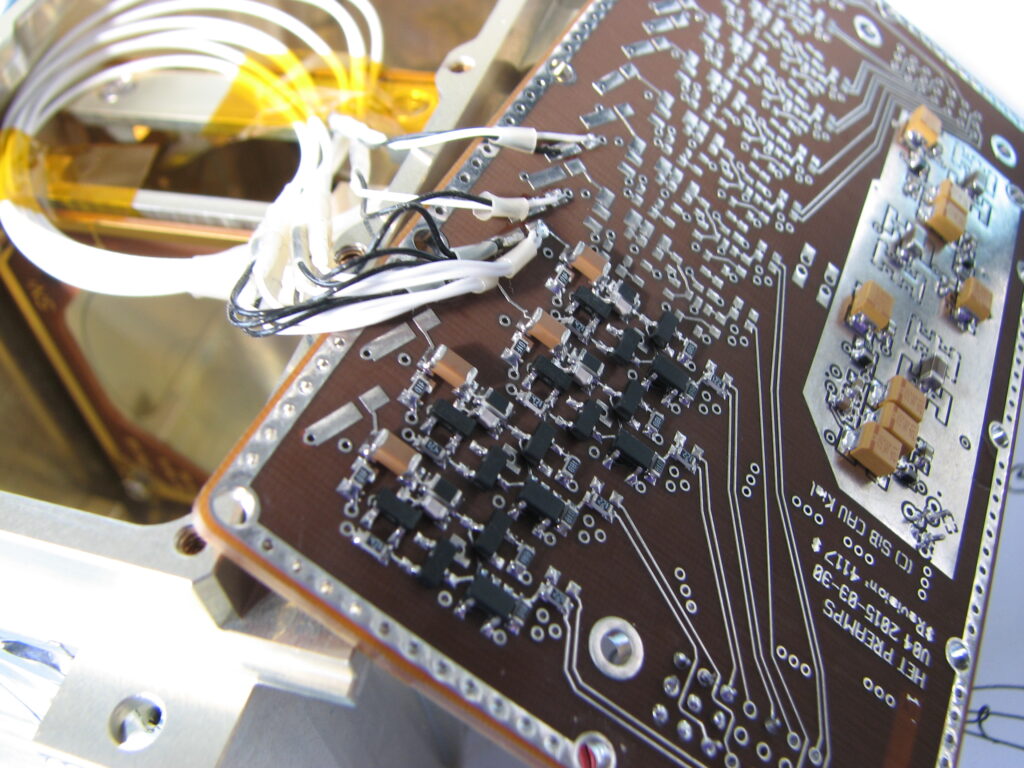
One of two big BGO scintillators is mounted. Below the BGO is the HET-AB double SSD stack. On the top is one layer of trigger SSDs, 20 Hamamatsu photodiodes, 1×2cm² each. The electronics for the other slice is connected and operational, but kept outside the box without sensors, for now.

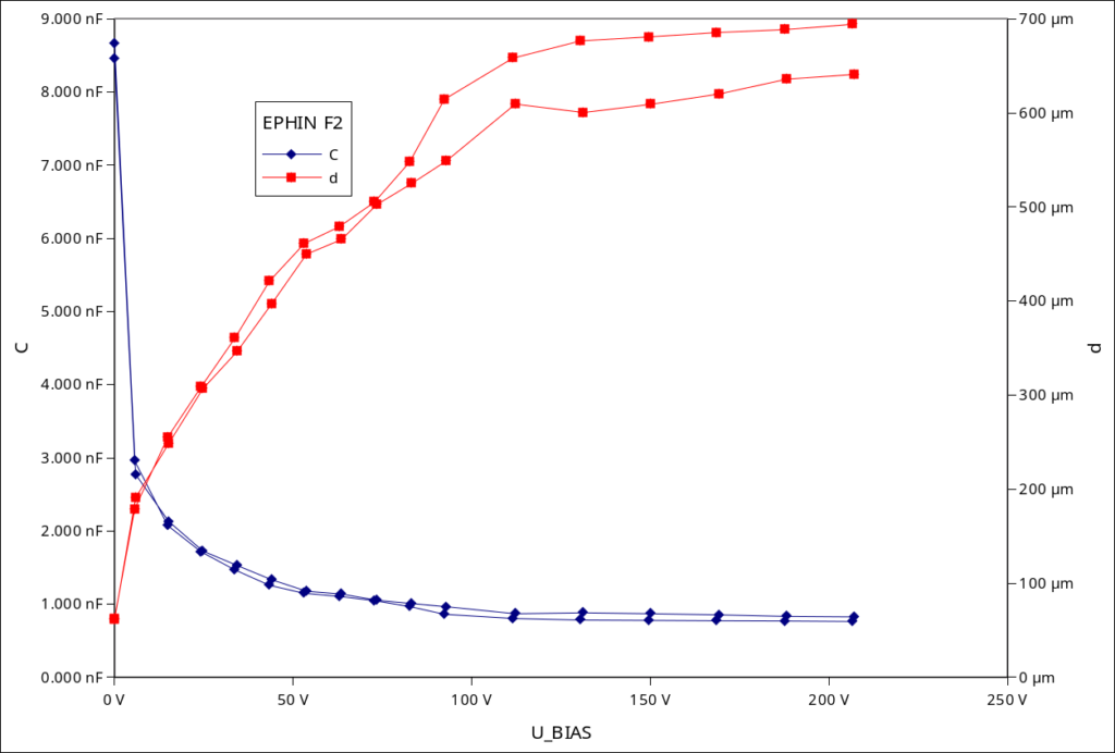
The first night of data is in, cosmic muons penetrating the sensor, and a pulser generating a calibration charge pulse (200fC) into the preamplifiers once per second.
On the left you see the energy loss spectra of the cosmic muons. The muons loose about 100keV energy with a path length of 300µm in silicon. The resulting charge signal is around 4fC, or 25000 electrons.
The BGO is 20mm thick, resulting in minimally ionizing energy loss of 19MeV. The emitted scintillation photons are collected by six photodiodes, connected to three preamplifiers, giving larger peak height, due to the enormous size of the BGO.