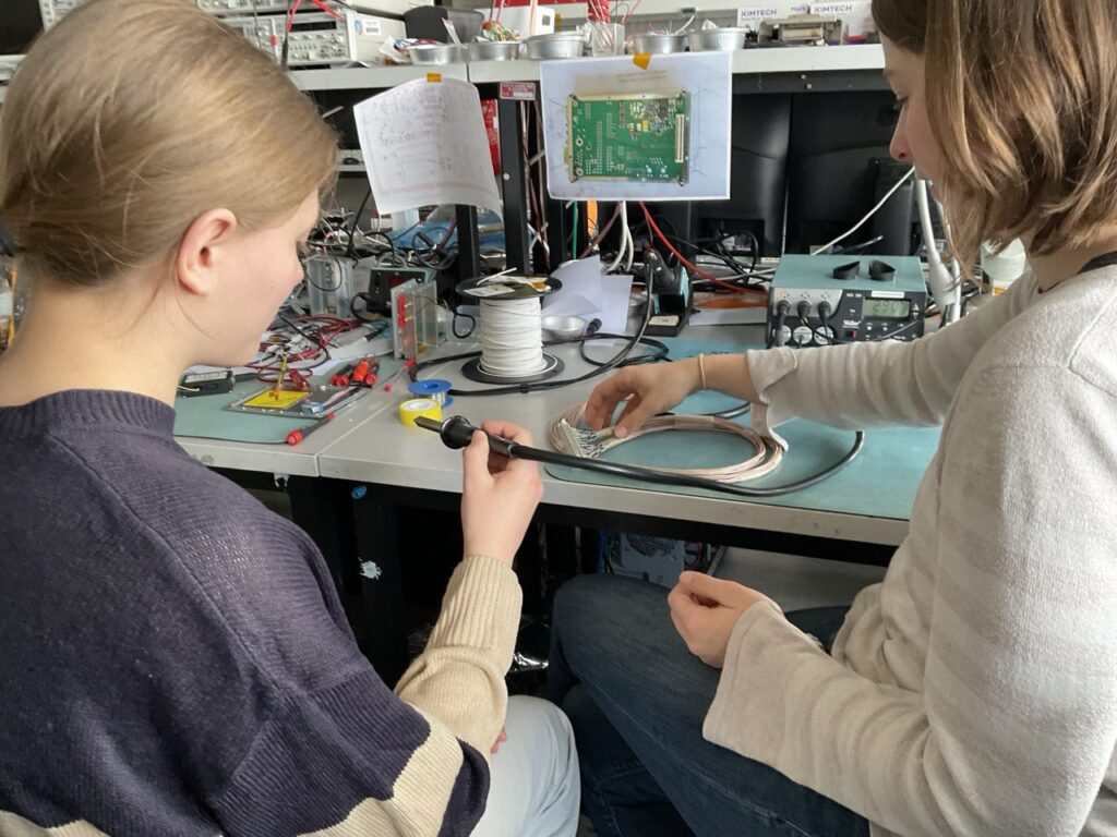
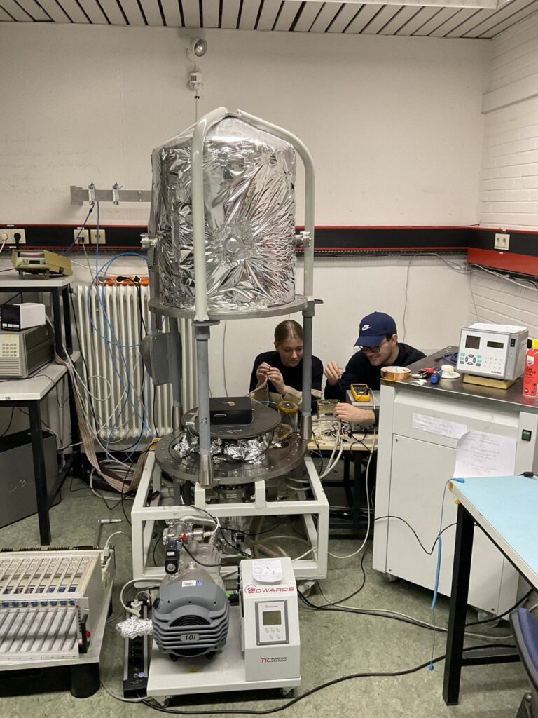
On Thursday 25 April, two schoolgirls visited us as part of Girls’ Day. In the morning we inspected the room in our building and glued one of the photodiodes to the bismuth germanium oxide scintillator. Then we showed and explained two of our current experimental setups. The set-up with the BGO crystal was going to be placed in the vacuum chamber. Together with the students, we took all the necessary precautions and transferred the whole setup to the laboratory with the vacuum chamber. In preparation, several cables were soldered from the test cell to the vacuum feedthrough and further to the readout electronics. These were extensively tested by the girls before commissioning, as were all the other feedthroughs and the power supply. After the lunch break, the measurement setup was put into operation and after successful tests, the vacuum chamber was closed and the air pumped out. As the light output in the BGO is temperature dependent, the next step is temperature calibration. Unfortunately, there is currently a problem with the cooling system, so this test will be delayed. However, with the help of the two students, the test setup in the pump-down vacuum chamber was successfully put into operation.
The heart of our experiment CHAOS is the Cherenkov detector. High energy particles travelling through this detector will create photons and because only few photons are created, a Photomultiplier Tube (PMT) is needed to detect them. This makes the use of High Voltages (HVs) necessary to operate the PMT and poses a security risk for our experiment. During the BEXUS balloon flight CHAOS will be exposed to low pressure environments. The combination of high voltages and low pressures can lead so-called corona discharges which could possibly harm the experiment. The easiest way to mitigate this risk is to place the experiment inside a pressure housing which ensures the same ambient pressure as on ground.
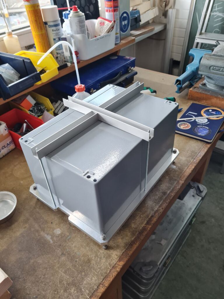
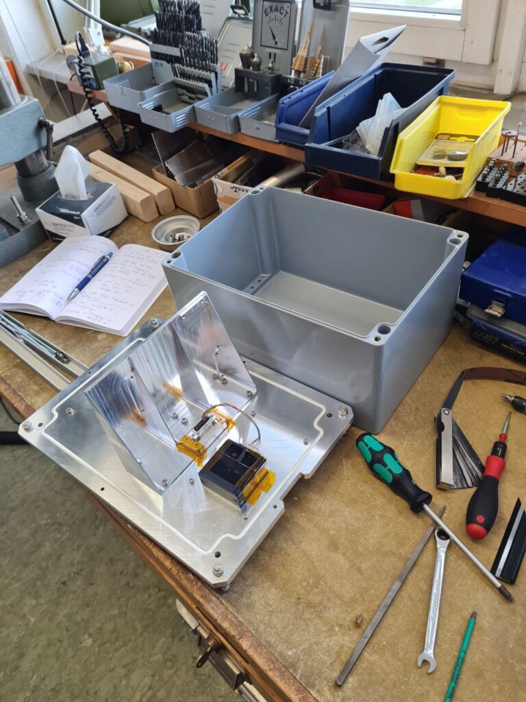
Here you can see the CHAOS pressure housing. It consists of an aluminum base plate on which a die-cast aluminum box is screwed. We use two additional U-profiles which press the box onto the base plate.
But we cannot simply put our pressure housing onto the BEXUS balloon. First, we have to prove that our design really works. This is why we performed several tests:
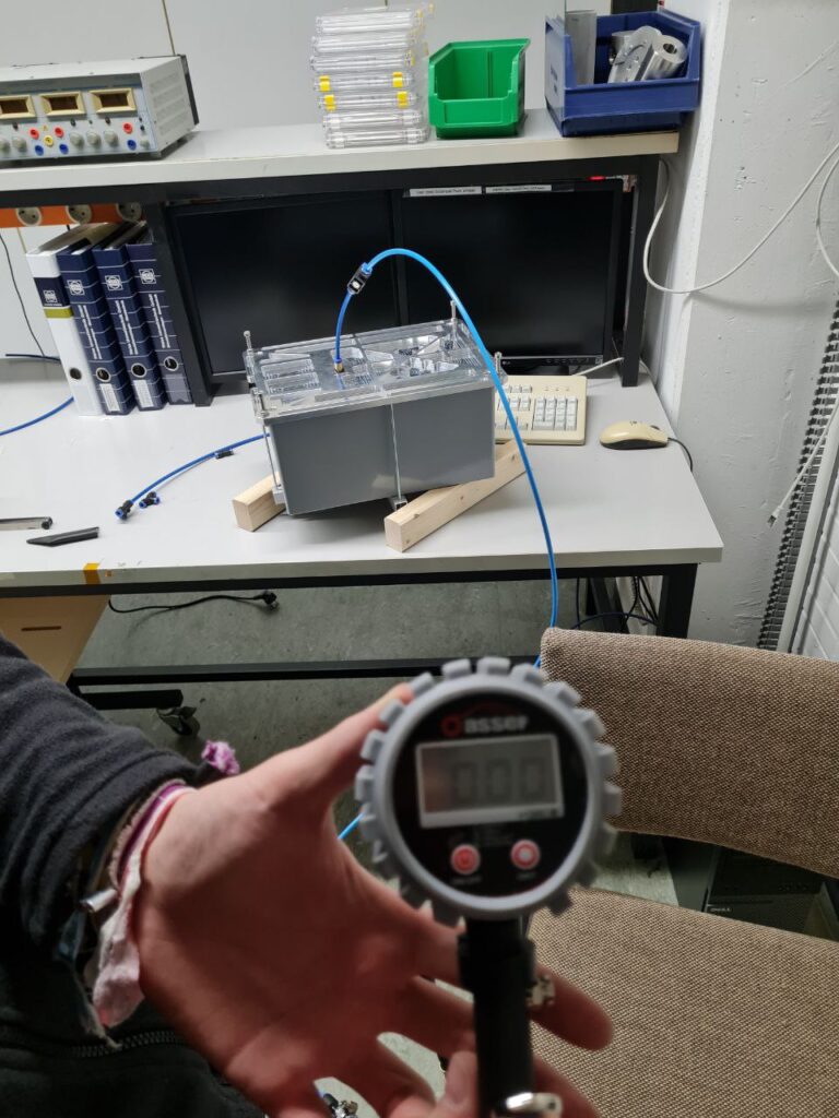
In a first step, we inflated our pressure housing with a tire inflator. Maybe not the most scientific way, but it worked. Sometimes scientists have to be creative. We were able to show that our pressure housing has no problems to withstand an additional pressure of 1.2 bar. During the BEXUS balloon flight the maximum pressure difference between the inside and outside of the pressure housing can be 1 bar.
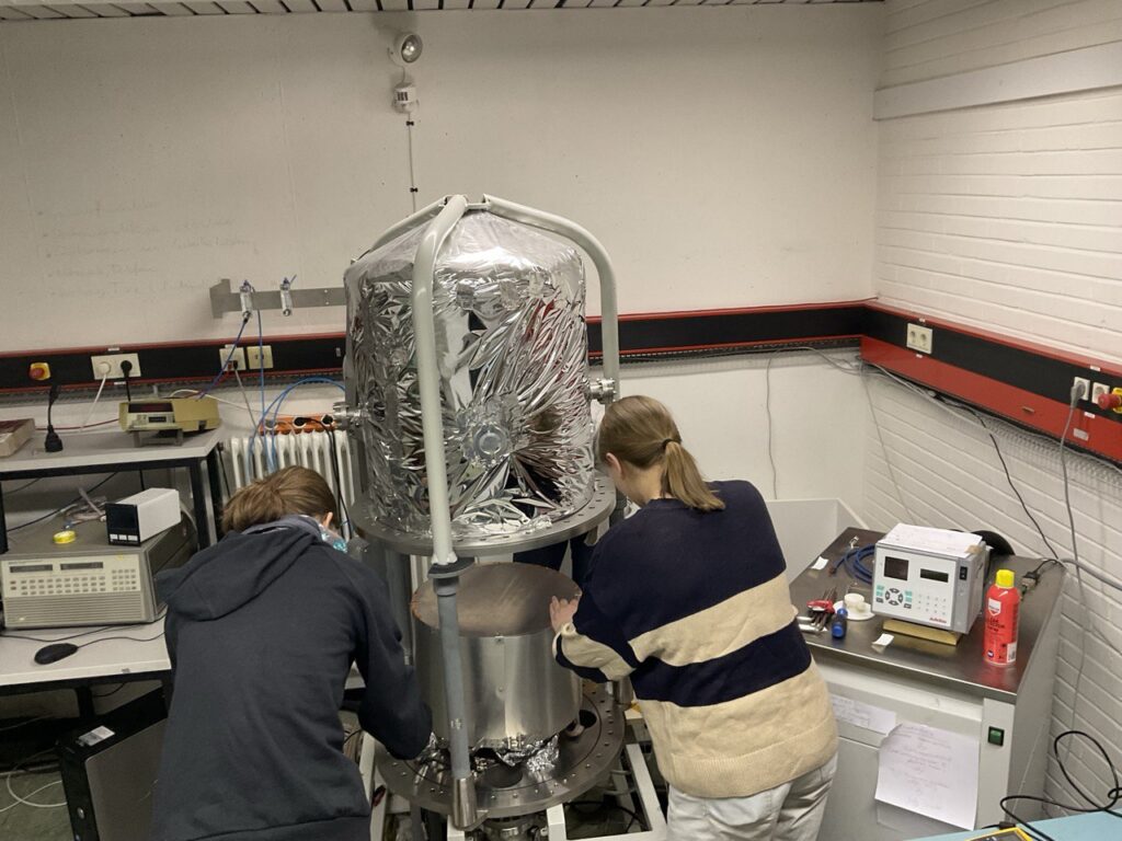
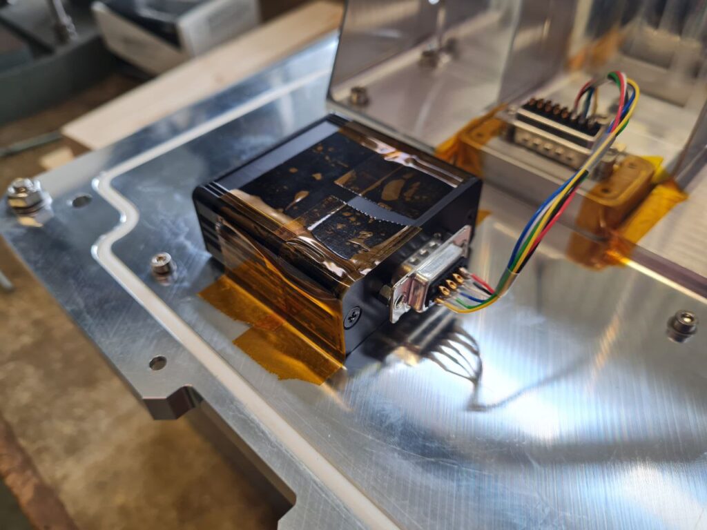
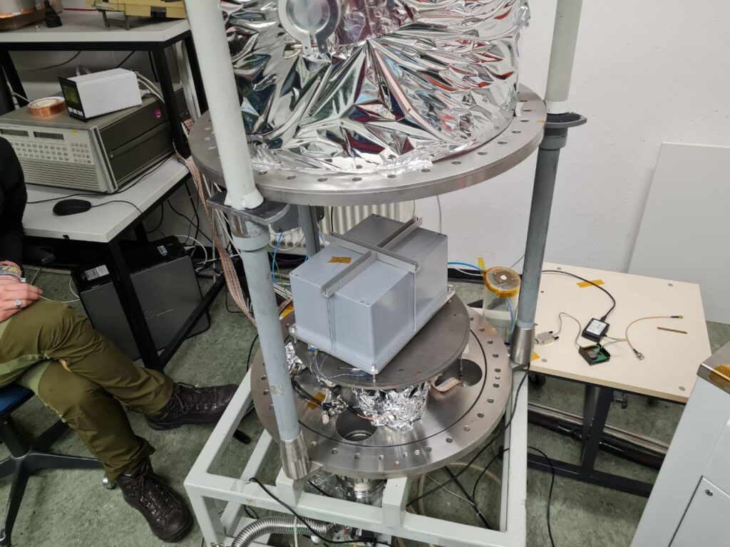
But that was not enough. We decided to put our experiment in the vacuum chamber at our university to perform a professional vacuum test. For the test we placed a pressure sensor inside the pressure hosuing as seen in the following pictures:
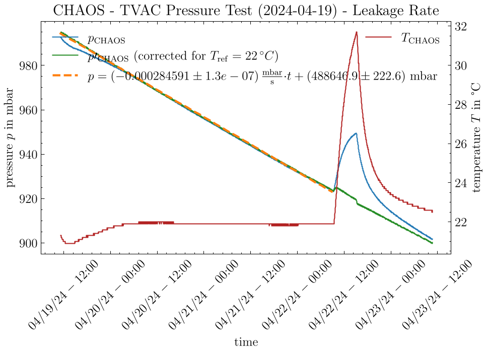
The pressure housing was put in the vacuum chamber which was then evacuated to a pressure of 0.1 mbar. We left the pressure housing inside the vacuum chamber for a total of four days. The results can be seen in the following plot:
The red curve is the temperature inside the pressure housing and the blue curve the pressure. The big spikes in temperature and pressure are caused by the heating plate inside the vacuum chamber which we turned on for several hours. The measured pressure was corrected for the temperature using the ideal gas law. This is the green curve. We can see a linearly decreasing pressure. This leakage was expected because a perfectly airtight pressure housing is hard to build. But we only lost around 100 mbar in four days. This is totally acceptable because the BEXUS balloon flights only last several hours. To quantify our results, we performed a linear regression on our pressure measurements. This regression was then used to calculate a leakage rate of around Q = -0.003 mbar*l/s.
We are very happy with the results of our tests. Hopefully, they will convince the board of experts at our Critical Design Review (CDR) as well. The CDR will take place at ESTEC in the Netherlands in May. So, stay tuned and follow us on our journey!