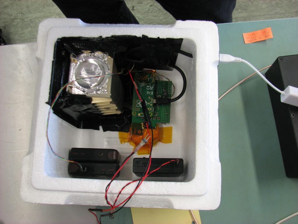
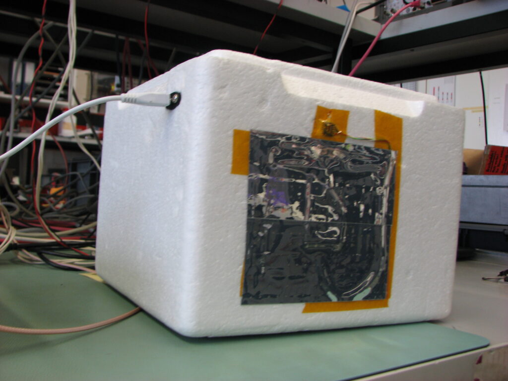
The sensor head for the CHAOS-Junior weatherballon mission was put in the styrofoam box. The area was made light tight with black ducttape. The CPU of the Raspberry Pi Zero and the FPGA of the RPiRENA DAQ board were glued to copper bands that extend through the styrofoam, where another copper foil was placed outside. The copper bands were fixed with copper tape and covered with a second surface mirror foil used for space missions. That foil emits heat radiation but reflects sunlight. Two GPS trackers and a battery box were placed in the box. One of the GPS trackers sends the NMEA messages to the serial port of the Raspberry Pi (via the FPGA), to be recorded in the data file. A STRATO3 datalogger will be added. Maybe we will find a camera to add as well. The Raspberry Pi is online.
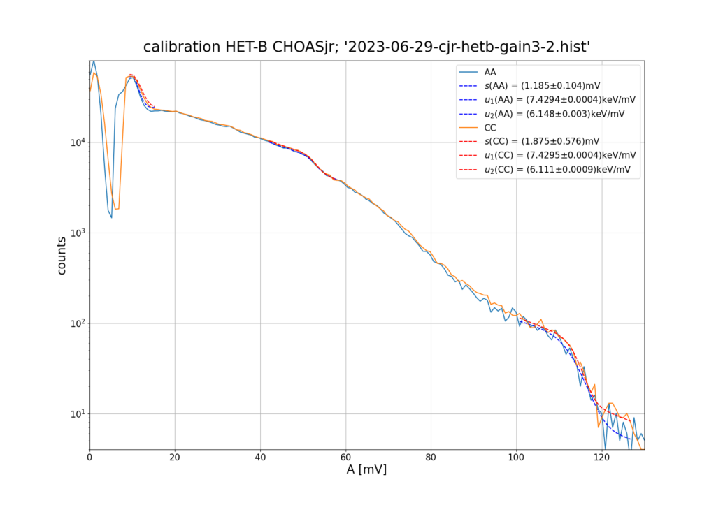
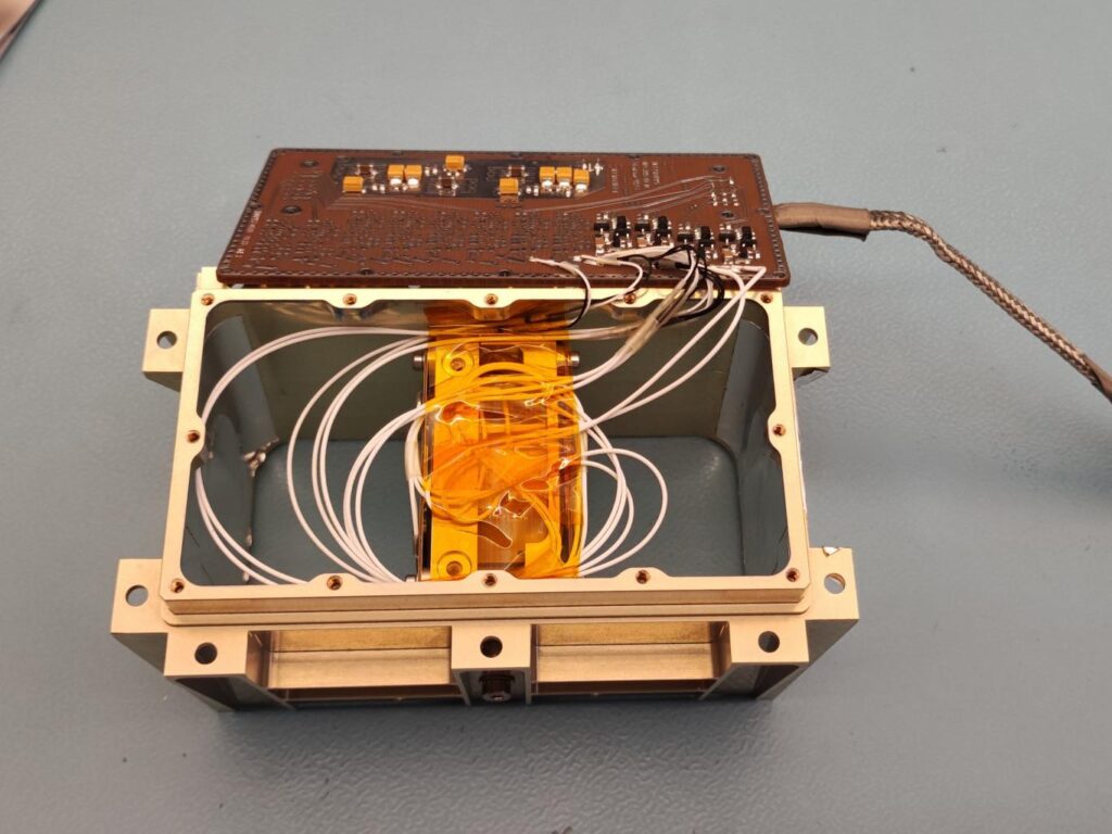
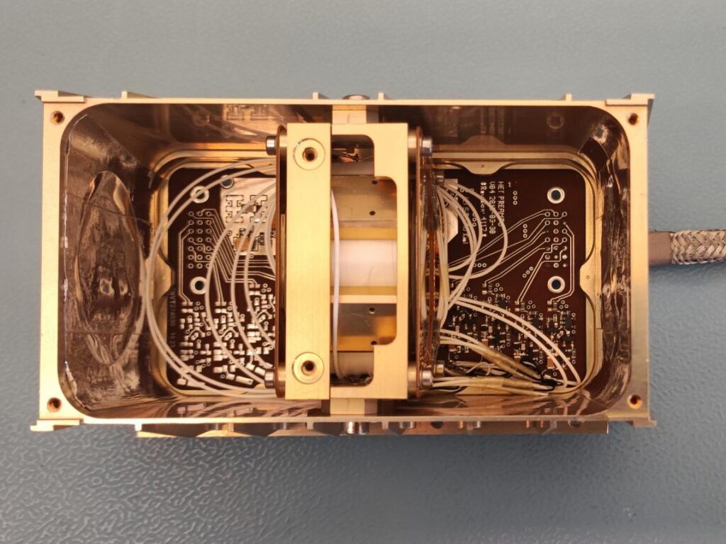
CHAOSjunior is a reduced version of the CHOAS experiment. The sensor head consists of a scintillator of Bismuth Germate Oxide (BGO) and two silicon detectors taken from High Energy Telecope (HET-B) in front of and behind the BGO. Two photodiodes were glued on the hexagonal BGO at opposite sides. The energy deposited in the detectors is proportional to the signals from the detectors. During configuration, the calibration parameter is determined. For this purpose a radioactive source of bismuth isotope 207 Bi is used. The characteristic lines of this source are known relatively precisely and can therefore be used for the calibration. First, the calibration of the HET-B detectors was carried out without BGO. The calculation of the channel names was chosen in following way. CHAOSjunior basically consists of three detectors, one HET-B, the BGO and another HET-B. These are named A,B and C in the direction of particle pass through. The information from the BGO (B) is shared between two channels. These are designated B1 and B2. The two HET-B detectors have only one channel each, these are designated AA and CC respectively. For calibration of preampfilters the sensor units were stimulated by a radioactive source of bismuth isotope 207 Bi. This isotope was placed in front of the sensor head. The prominent emission lines were taken from NUDAT3 (https://www.nndc.bnl.gov/nudat3/ ). The Compton effect of the γ lines at 569.698 keV and 1060 keV could be well observed for both HET-B signals where the first edge is much more precise. The data recorded was adapted by three models, one for the x-ray peaks and one for each Compton-edge. The models deliver the noise s and the calibration parameters u, which allow the conversion of the signals into keV.
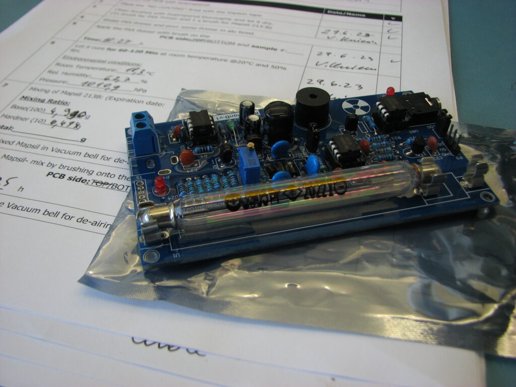
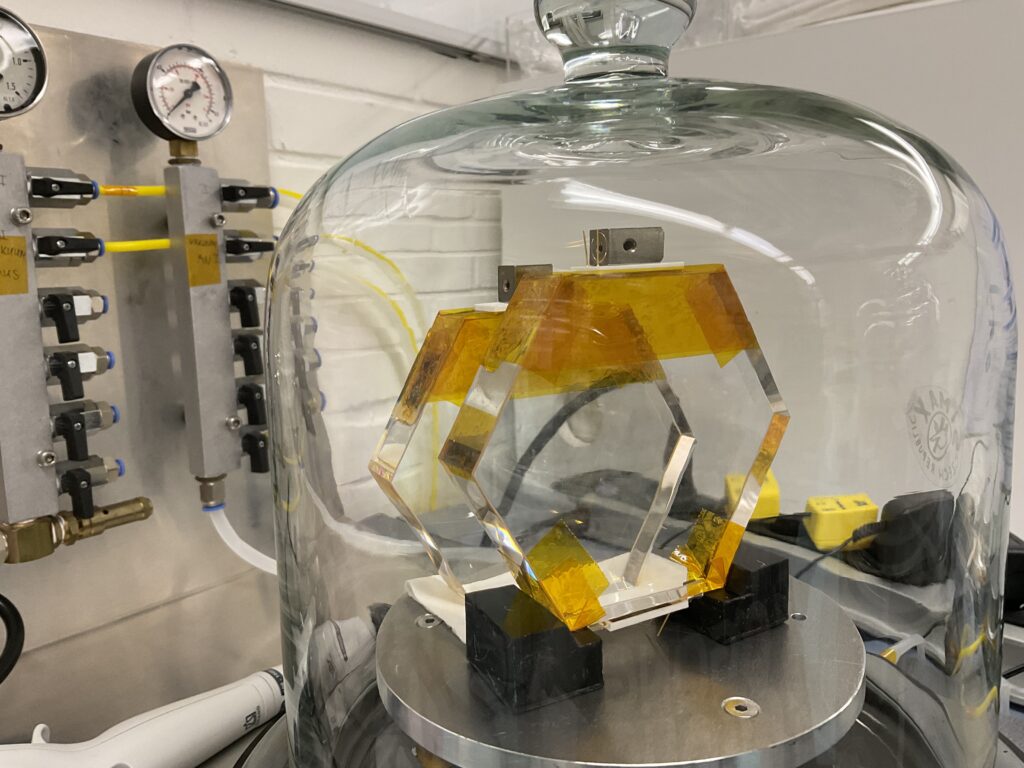
For a Weatherballoon mission lead by the Ricarda-Huch-Schule we prepared and tested a Geiger-Müller Counter module. The challenge is to operate the high voltage supply of the tube in the partial vacuum of the stratosphere. We may encounter a Corona discharge, which may destroy the electronics or at least impact the measurements. We are all happy to leave Corona behind us. The second issue is the internal pressure of the tube. We passed all tests. Down to 1mbar pressure the unit worked flawlessly.
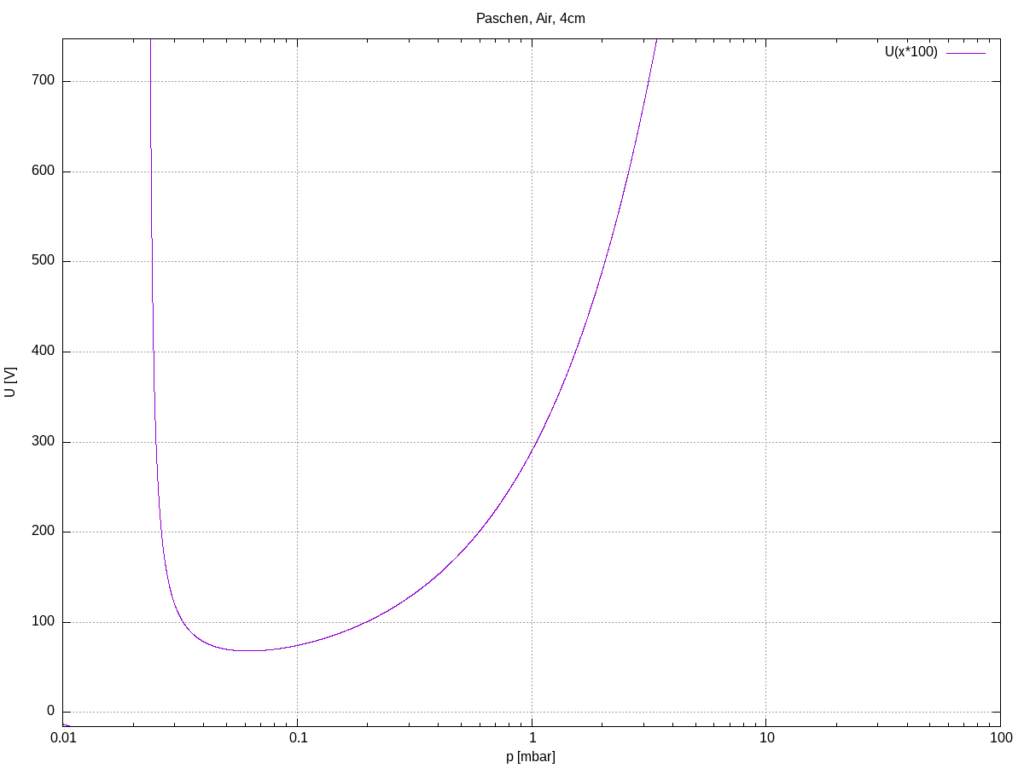
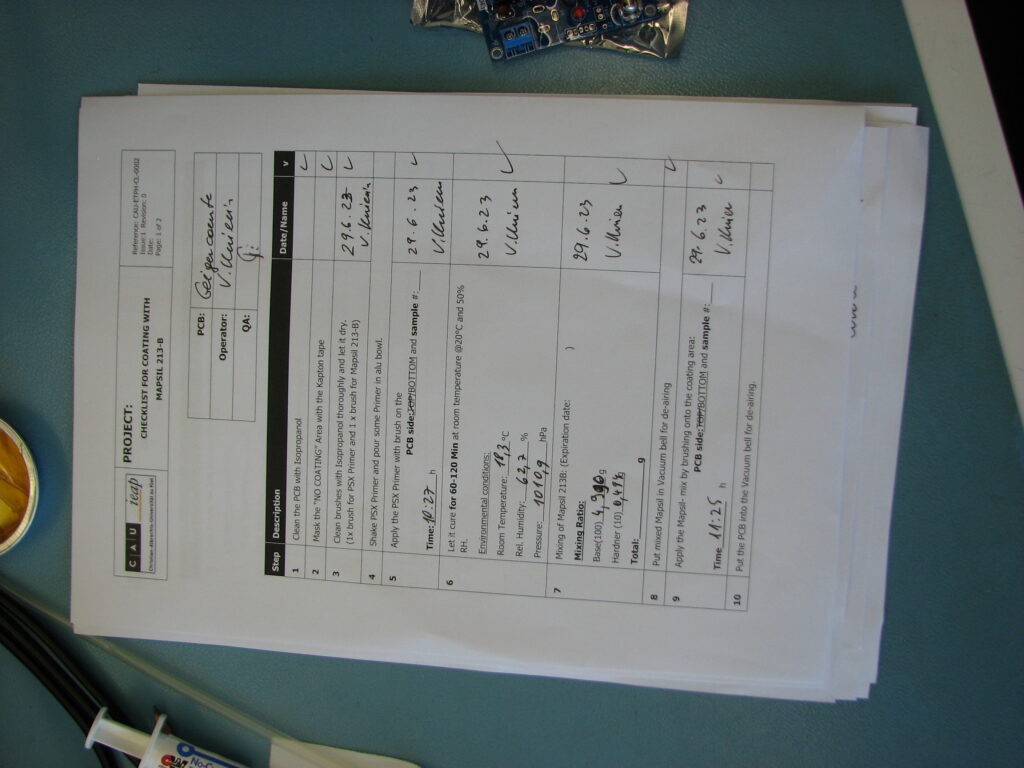
First, the tube was tested individually. It survived low pressure. The HV was calibrated to 400V as prescribed in the manual. Then we removed the calibration connecter and a power connector that were too close to the HV electrode of the tube. The board was coated twice with a space grade 2-component silicone encapsulant, in particular the HV supply and the area close to the HV end of the tube. We obtained an insulation distance of about 4cm.
The Paschen Curve tells us that we should be good down to a few mbar.
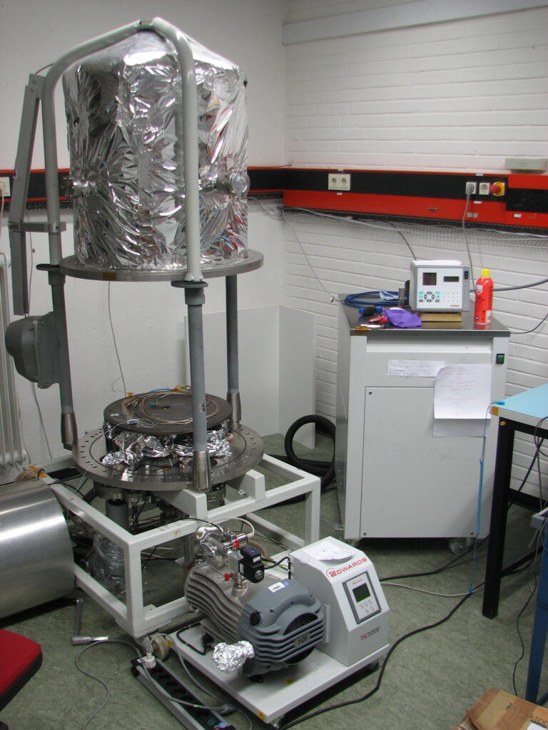
First, we tested in a glas chamber, to visually observe the test. But that pump could not go below 60mbar. Then we used our regular thermal vacuum test stand for balloon missions, shown above. The test was performed at room temperature. We used only the rough vacuum pump, which took the chamber pressure down to 1mbar. The output of the module was monitored with an oscilloscope. A ²⁰⁷Bi souce was place inside the chamber to increase the counting activity. It worked well. Unfortunately, we did not take any pictures.
Vio did the coating, see the log sheet above. Ronja soldered the feedthrough harness and performed the Vaccum tests. Sönke observed radiation safety. Matti provided the counter module.
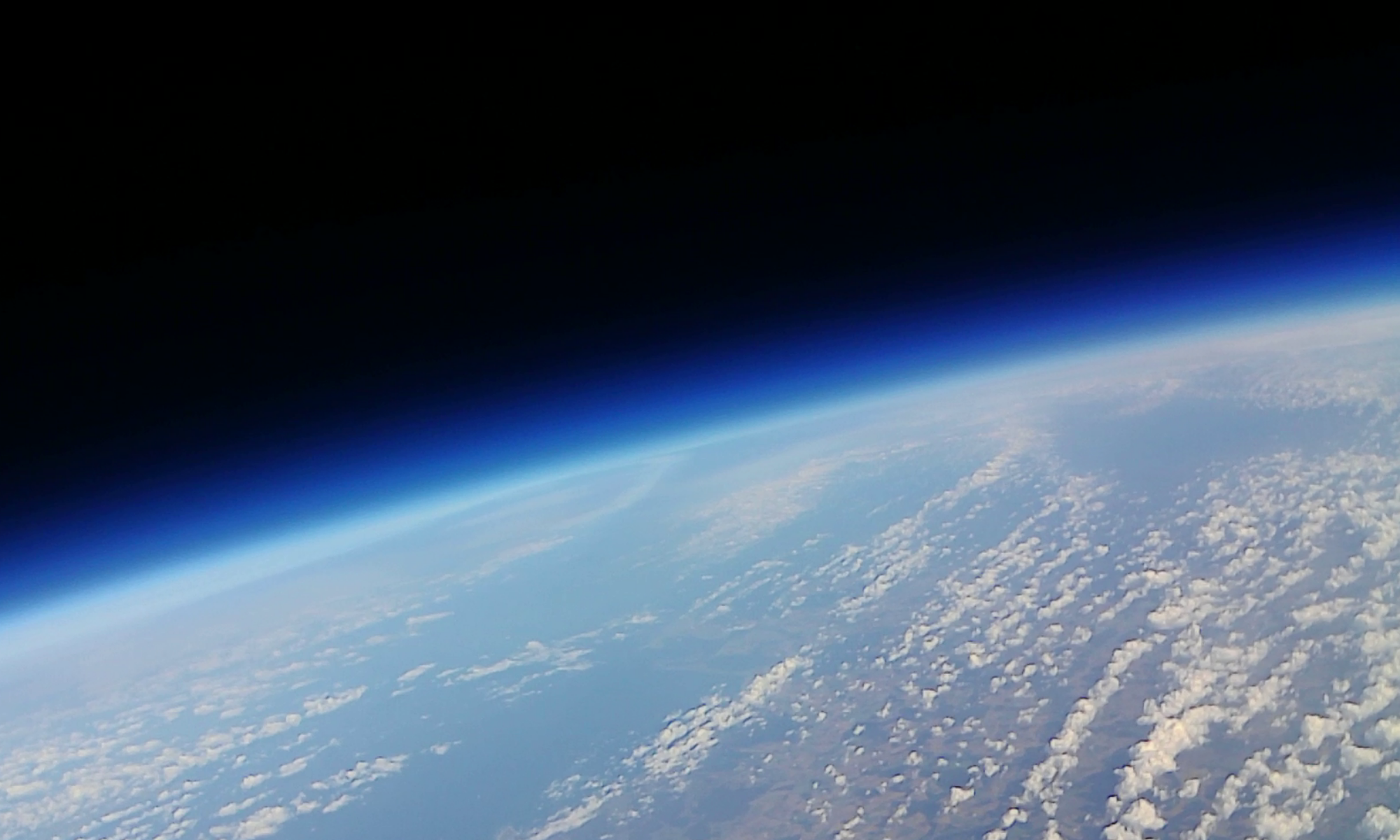
Now we are waiting for the flight forecasts to predict a landing site on land.
Last week the big BGOs have arrived. One alone weighs over 1kg. Currently, two BGOs are covered with photodiodes. One with two on opposite sides and one with three each at an angle of 120 degrees. Subsequently, the dependence of the light output (sum of the diode signals) on the number and arrangement of the diodes is to be determined experimentally.
After performing a calibration measurement for the two HET-B detectors, the BGO was now also integrated into the sensor head and the two glued-on diodes were connected to the two free slots on the preamplifier board. The gain was changed to 3 in advance. Additionally two temperature sensors were connected. One measures the temperature directly at the BGO mount, the other is intended to look out of the box during flight and measure the environmental temperature.
Trigger thresholds for each channel were set to 5mV. In coincidence, the two BGO diodes trigger from even 3mV. First measurements are running and results will follow shortly right here.
Today we have submitted our letter of intent to the BEXUS program marking our first steps to a possible participation in the next BEXUS-cycle
Our instrument CHAOS (Cherenkov Atmospheric Observation System) represents a scaled-down version of the ATHENA High Energy Particle Monitor (AHEPaM), which is designed to measure the background radiation of the ATHENA mission.